Harsha Engineers · Project Report
Designing an Automated Part Feeding System
The aim of this project was to design an automatic part feeding system for a specific stamping operation. The work included understanding the requirements, choosing a suitable design, carrying out engineering calculations, and selecting the main components.
Problem Statement & Requirements
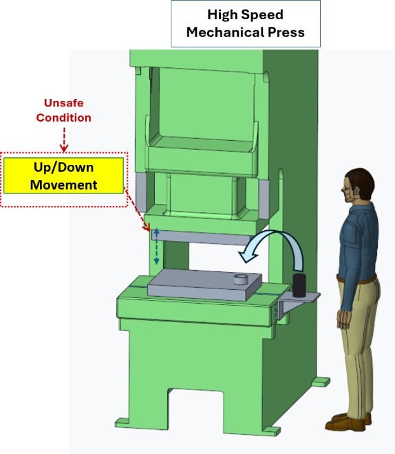
Loading rings by hand into a high-speed mechanical press creates unsafe working conditions. During manual loading, the operator works close to the press as it moves quickly up and down, creating a high risk of injury. Although safety measures are in place, manual loading cannot keep up with the machine's speed and accuracy requirements, which also reduces efficiency.
Key requirements
- Use an automatic ring feeding system or a robotic loader
- Required loading rate: 60 parts per minute
- Sheet metal rings: outer diameter up to 90 mm, thickness up to 1.5 mm, weight up to 30 g
- Rings are supplied in stacks, which are the input for the pick-and-place mechanism
Concept Selection
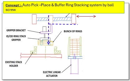
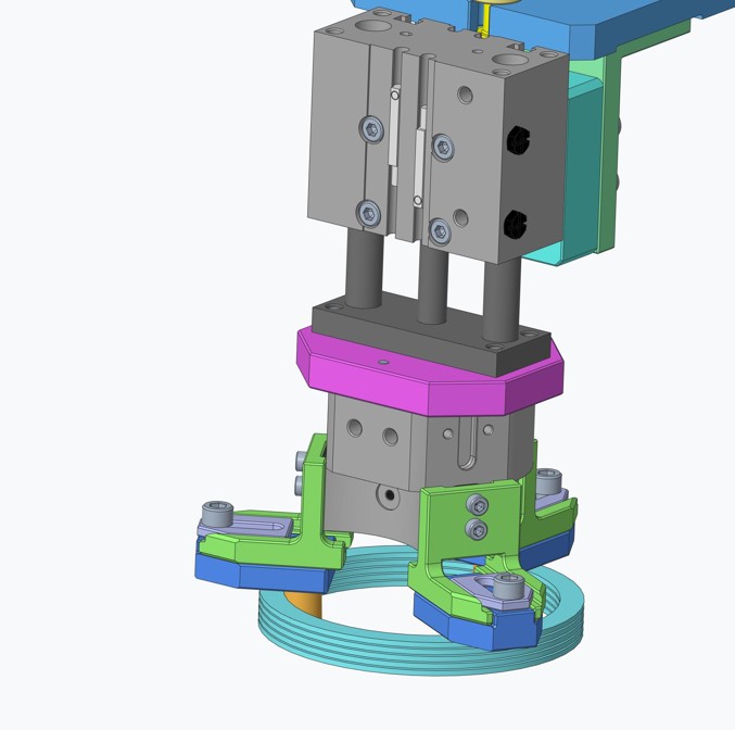
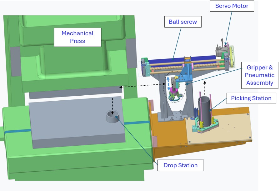
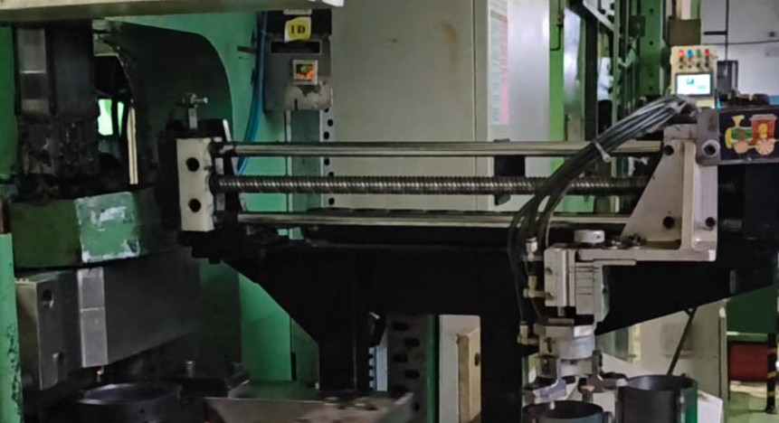
Several design ideas were compared on speed, cost, and part standardisation. A ball-screw-based pick-and-place system was selected for detailed design. A ball screw and servo motor move the system along the X axis, while a pneumatic mechanism provides movement along the Y axis and lets the gripper hold and release the rings.
- Smooth and precise movement
- Vibration-free, even with an off-centre load
- High-speed operation
- Simple and easy operation
Design & Subsystem Selection
Ball screw inputs
| Parameter | Value |
|---|---|
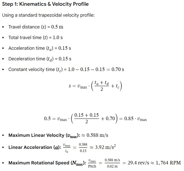
| Travelled distance | 500 mm |
| Travelling time | 1 s |
| Moving mass | 16 kg |
| Ball screw diameter × pitch | 20 mm × 20 mm |
| Ball screw length | 702 mm |
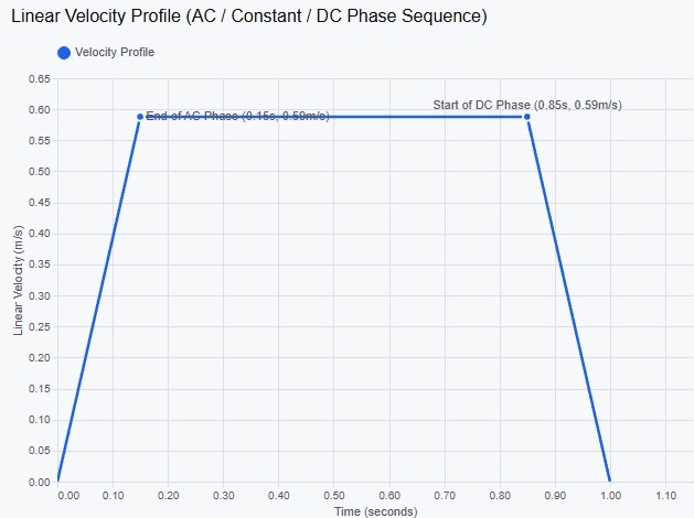
| Acceleration / deceleration | 0.15 s each |
| External force on gripper | 200 N |
| Guide rod coefficient of friction | 0.1 |
| Ball screw orientation | Horizontal |
Calculations
Motion was planned using a trapezoidal velocity profile, followed by force, torque, inertia and power sizing.
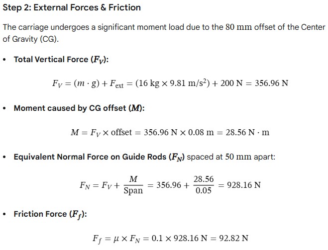
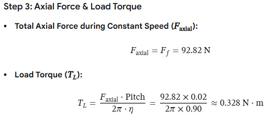
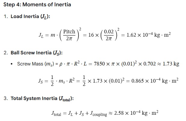
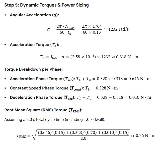
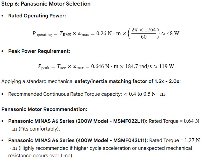
Motor selection: a 400 W servo motor was selected to drive the ball screw.
Gripper selection
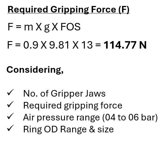
| Parameter | Value | Status |
|---|---|---|
| Part weight | 0.9 kg | Input |
| Required factor | 13× weight | Criteria |
| Required force (Fr) | 114.77 N | Target minimum |
| Gripping point distance (L) | 30 mm | Input |
| Min air pressure | 5 bar (0.5 MPa) | Input |
| Required stroke (per side) | 4.0 mm | Input |
| Model | Specification | Result |
|---|---|---|
| MHS3-25D | Bore 25 mm · ~42 N | Failed — insufficient stroke & force |
| MHS3-32D | Bore 32 mm · ~74 N | Failed — insufficient force |
| MHS3-40D | Bore 40 mm · ~129 N | Recommended — optimal stroke & safety margin |
Final Design
The final design was developed using the selected concept and the calculations.
Conclusions & Learnings
After the trial run, data was collected on how often operators needed to step in and how many operators were required.
Ring feeding actions per hour
Operators per press
- The pick-and-place system met all the objectives set for the project.
- The unsafe manual loading condition was eliminated — operators only replace the large stacks of rings, away from the moving parts of the press.
- Ring feeding actions needed per hour fell from 450 to 12.
- Staffing saving of 1 operator per shift per press — one operator can now handle 2 presses.
References
- smcin.com
- industry.panasonic.com
- thk.com